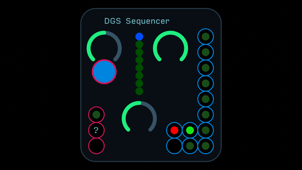
The DGS Sequencer allows you to create distinct and rhythmic gates or clock signals. Instead of being driven by a clock, it is driven by an LFO at the lower left unlabelled input.
An LFO value of 0 is the beginning of step 1, and a value of 1 is the end of step 8.
The top left knob is the step selector. When the knob is moved, a red current step indicator will appear. After a few moments of no change, or after pressing the step on/off button below it, it will disappear.
The right knob controls the maximum number of steps. The lights at the center of the module disappear as the max step length decreases.
The two DGS outputs between the red DS outputs and the column of 8 DGS outputs are the main output (lower) and inverted output (upper) of the DGS sequencer.
Next to these outputs, in red, is a slewed output, controlled by the knob at the center of the module.
The column of 8 outputs are the values of the 8 individual steps. Step 1 is on the top; Step 8 is on the bottom.
The top two inputs on the right of the module are there for remote control.
The DGS input flips the value of the current step (like the button above it).
The ? input is the step selector level (like the top right knob). It accepts a DS signal.